
Article posted: April 20, 2019
Added content: Shore Power Transformers; July 22, 2019
Added content: DC Electric Circuit “Wire” Naming and Identification; October 6, 2020;
Minor edits: October 6, 2020
Minor edits: February 16, 2021
Updated Diagrams: April 18, 2021
About this article
The AC Electricity Fundamentals – Part 1 article precedes this article and discusses 1) the concepts, terminology, components and layout of National Power Grid generating equipment, 2) delivery of AC power into residential neighborhoods, and 3) the configuration of AC electrical systems within a residential building, all at an introductory level. Boats attach to marina shore power systems. The shore power system is the “host system,” and boats attach as “appliances.” An understanding of residential AC power systems is foundational to an understanding of AC power systems on boats.
The Part 1 article concluded by showing that the AC shore power system on boats is equivalent to a sub-panel in a terrestrial building. In the NEC architecture of terrestrial AC building systems, sub-panels are subordinate to the main service entrance panel of the building. In the same way, boats are subordinate to the shore power AC electrical infrastructure of a terrestrial facility.
This article focuses on the overall AC electric “platform” aboard cruising boats. On boats, shore power is only one component of a typical AC system “platform,” which can also include a mix of onboard generator(s), inverter(s) and in some cases, shore power transformer(s). This introductory Part 2 article will answer some questions, and will undoubtedly raise others. The goal of this article is to help readers understand AC electrical concepts and topics to be able to discuss questions, concerns, symptoms and options with marine-certified, professional electrical technicians.
Personal Safety
Virtually all electricity can be dangerous to property and life. Even de-energized electrical circuits can retain enough stored energy to create a life-threatening hazard. This is especially true of inverter-chargers. The large batteries found on boats can produce explosive gasses and store enough energy to start a large, damaging fire.
ALWAYS WEAR SAFETY GLASSES while working around electricity! Anyone working in noisy environments, with running engines or other loud machinery, MUST WEAR HEARING PROTECTION.
If you are not sure of what you’re doing…
If you are not comfortable with electrical safety procedures…
If you are not sure you have the right tools for a job…
If you are not sure you know how to use the tools you do have…
Well, then, LEAVE IT ALONE until you learn more!
Electrocution
Electrocution is a biological insult arising from an electric shock that paralyzes either the respiratory or cardiac functions of the body, or both. Electrocution results in death. Even very small electric currents, under the right circumstances, can result in electrocution. Obviously, electric shock can be a life threatening emergency.
If you are present and witness an electric shock or electrocution, in any locale around boats or water, there are several things that need to be done immediately. Remember, since the victim is not breathing, you’ll have 5 minutes or less to accomplish items 3 – 10, below:
- STAY CALM! You can not save someone else if you panic!
- Avoid becoming a victim yourself! DO NOT TOUCH THE VICTIM, METAL MACHINERY OR NEARBY METAL OBJECTS IF POWER IS STILL PRESENT!
- SCREAM FOR HELP! ATTRACT ATTENTION! Point at the first person who’s attention you get and instruct them to “call 911 for an electrocution!”
- REMOVE THE POWER SOURCE FROM THE VICTIM BY DISCONNECTING THE ELECTRIC POWER at the pedestal.
- If the victim is in the water, KILL POWER TO THE ENTIRE DOCK.
- THROW LIFE RING TO VICTIM. DO NOT ENTER THE WATER YOURSELF!
- After power is removed, raise the face of an unconscious victim out of the water.
- After power is removed and the victim’s airway is secured above water, if help has not arrived, call 911 again! Two 911 calls are better than none.
- After power is removed, and with access to the victim, assess victim and initiate CPR as appropriate. CPR is often successful in reviving or saving electrocution victims who are otherwise healthy at the time of the accident.
- CONTINUE CPR UNTIL THE VICTIM REVIVES, UNTIL EMS ARRIVES TO RELIEVE YOU, OR UNTIL YOU ARE PHYSICALLY UNABLE TO CONTINUE!
Boat Electrical System – Scope
Viewing the shore power AC system of a boat as a residential sub-panel in a single family residence is simple and technically accurate, but the AC electrical system of a typical cruising boat is more than just shore power. A simple block diagram of a boat electrical platform can show the relationships among the various components of the boat’s AC (and DC) electrical systems. Sanctuary’s energy flow diagram is shown in Figure 1. This diagram shows Sanctuary as she is today. When we bought her, she did not have a genset, she did not have an inverter-charger, and she was fit with two inappropriate battery banks. She was less complex yet poorly designed for our intended use.

Figure 1 shows Sanctuary’s AC and DC electrical systems as a complete and integrated operational “platform.” From the platform perspective, owners can evaluate the impacts of contemplated alterations and upgrades. The diagram shows energy flow, not wiring detail. Its simplicity allows one to visualize and understand both individual components and how components feed and are fed by one another. It is all too easy to add, remove and change system components without fully appreciating the impact(s) to the overall host electrical platform.
Sanctuary’s OEM factory configuration consisted of two 8D batteries, one dedicated to engine starting, and the other dedicated to modest OEM space and navigation lighting loads. An 8D was excessive and poorly utilized for engine starting, and inadequate for our house needs. The energy flow diagram gave us the ability to visualize the impacts of consolidating the two separate battery banks into a single bank.
Sanctuary’s OEM factory battery charger was an obsolete technology single-stage unit. We wanted AC power aboard without having to run our genset. We decided to change the battery charger to a fully automatic inverter-charger. This was a major upgrade that affected both the AC and DC electrical systems aboard. Mechanically, the upgrade was simple, but modification of branch circuit wiring to comply with the ABYC electrical standard was a big impact to our host AC electrical system.
Adding a new genset to a boat includes adding a Generator Transfer Switch and reworking the distribution wiring of the existing shore power circuits. Replacing an old-iron 60Hz AC genset with a new 60Hz AC genset would be relatively easy and non-disruptive. Converting to a DC genset (a diesel-driven DC battery charger) has very different implications. Cost, technical complexity and value of the alternatives can be compared and evaluated.
The energy flow diagram shows that Sanctuary is now fit with a single battery bank for both “engine start” and “house” support. Adding a wind generator or adding solar panels are energy management solutions that would have technical impacts to the existing system. Each can be evaluated from the perspective of our energy flow diagram. Boat owners are strongly encouraged to take a “platform view” as opposed to a “component view” of the electrical systems on their boats.
High Complexity Aboard Boats – Power Sources
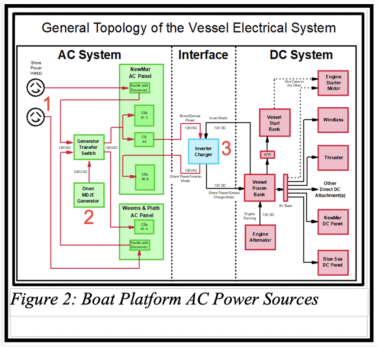
What is immediately clear from Sanctuary’s energy flow diagram is that there are three entirely independent AC sources that can feed power to our onboard AC loads:
1. shore power (source ashore),
2. generator (source aboard),
3. inverter, (source aboard) and on some boats,
4. shore power transformers (source aboard) (not installed aboard Sanctuary.
DC Electric Circuit “Wire” Naming and Identification
In DC circuits on boats, the conductor carrying the positive charge is called “B+,” and also called the “plus” or “positive” conductor. By conventional agreement, the positive DC conductor is red in color. The conductor that returns current from the load to the source is called the “B-,” or “negative” conductor. By conventional agreement, the negative conductor (in 2020) is yellow in color. Until recent years, DC negative conductors on boats had black insulation, and many such systems are still in service today. In boats with both DC and AC systems installed, the black DC negative wire was easily confused with the black AC energized wire, so the ABYC color code for DC wiring was changed to yellow to eliminate the safety implications of confusing those two wires. In DC situations, the “negative,” or “B-” conductor is sometimes referred to as a “ground,” although that is usually (often) not technically correct, since “ground” wires are not intended to carry current.
Key points from the Part 1 article to keep in mind on boats: In AC circuits, the conductors are alternately positive and negative, so the DC nomenclature “B+” and “B-” doesn’t work. In single phase 120V circuits in North America, the two conductors are named for on their role in the circuit. The conductor that is considered to be the energized (power suppling) conductor is called the “Ungrounded Conductor,” or “Line 1,” or the “hot” conductor. By code and convention in North America, “L1” is black in color. The other conductor in a 120V circuit is the return conductor. It is called the “Grounded Conductor,” or the “Neutral Conductor,” or simple the “neutral,” and it is white in color.
In single phase 120V/208V and 120V/240V circuits in North America, there are two “Ungrounded Conductors.” They are commonly called “Line 1” and “Line 2.” “L1” is black, and “L2” is red. In these circuits, there is also a “Grounded Conductor,” always referred to as the “neutral,” and white in color.
Subtle take-away: the DC “negative” conductor has the same role in a DC circuit the the AC “neutral” conductor has in a residential/boat AC circuit. That is, the DC “Negative” conductor returns current to the source. In a “grounded DC electrical system” (very rare) the B- conductor is a “Current-Carrying”, “Grounded Conductor.”
Note: on some but not all boats built overseas, AC wire colors may be different than the ABYC Standard colors cited above. On some boats, like some Grand Banks trawlers, one 120V “hot” conductor (L1) is black, but the other (L2) is brown, not red; and the AC neutral conductors are blue, not white. If “strange colors” are found aboard a boat, BE PARTICULARLY CAREFUL to determine what the colors mean to ensure ongoing equipment, fire and personal safety.
Key Electrical Concepts For AC Services aboard Boats
Key points from the Part 1 article to keep in mind on boats:
- “Shore power” arises from the electrical system of a terrestrial facility, ashore, while AC power from a “generator,” “inverter,” and/or “shore power transformer” arises from equipment installed aboard the boat.
- The residential AC power standard in North America is a “Single Phase, Center Tapped, Three-Pole” grounded-neutral system. This definition broadly applies to all terrestrial buildings with which people interact, and includes boats.
- State/Province, county and municipal jurisdictions across North America adopt local statutes and codes-of-regulations that originate with the NEC/CSA to govern terrestrial building electrical installations.
- There are no statutory electrical codes for boats. The American Boat and Yacht Council (ABYC) provides voluntary standards to boat builders. ABYC electrical standards are fully compatible with NEC shore power, assuring safe, reliable inter-operability between terrestrial and boat-resident AC systems.
As discussed in the Part 1 article, an essential safety requirement of all of these standards and codes is that single phase electrical systems be “grounded” at their “derived source.” This brings us face-to-face with some core ABYC “recommendations” that govern switching of AC wiring for equipment installations on boats:
- only one source is allowed to power loads aboard boats at any one time,
- sources must be thoroughly and completely isolated from one another,
- a “grounded neutral system” is required:
- when on shore power, the neutral-to-ground connection is provided to the boat through the shore power cord, (i.e., the neutral-to-ground connection is in the shore power infrastructure), and
- when on generator or inverter power, or when shore power is received through an onboard shore power transformer, the neutral-to-ground connection is made at the onboard source.
High Complexity Aboard Boats – Ground
In a “Single Phase, Center Tapped, Three-Pole” grounded-neutral system, what does “grounded neutral” mean? Recall in the residential AC system model that three conductors arise from the utility power transformer at the street; two energized lines (“L1” and “L2”) and one neutral line (“N”). As these three lines emerge from the utility transformer in the street, 240V are present between “L1” and “L2,” and 120V between “L1” and “N” and between “L2” and “N,” but these voltages “float” with respect to their external environmental surroundings (recall the discussion of birds and squirrels on wires from Part 1). This situation is referred to as a “floating neutral.” To create a safe, known zero-volt system reference, copper rods are driven into the earth at the building’s service entrance location. Within the main service panel of the building, the utility-provided neutral conductor is connected (“bonded”) to this network of copper ground rods. The result is an earth-ground “grounded neutral” system. The ground rod(s) reference the building neutral conductor to a very large mass at a zero-volt electrical potential (the Earth). This Earth Ground IS NOT the same as “circuit ground.” It would be the exception for a direct connection between L1 or L2 and the building’s ground rods to cause a circuit breaker to trip. That is the function of “Equipment Bonding Conductors,” NOT the ground connection. See my article on “Earthing and Grounding” on this website for more detail.
Grounding the neutral is very straight-forward at buildings. Since there is only one place where utility power enters the building from the utility company’s electric meter, it’s easy to understand and visualize that entrance location as the “derived source” of the power. Electrician’s working in terrestrial buildings learn to mix neutral and safety ground conductors on the same buss bars in the main service panel. In one of the examples I showed in the Part 1 article, we saw that some main service panels are built with only one buss bar which serves to collect both neutrals and grounds.
Boats are different! In the architecture of the North American power framework, boats are sub-panels to the shore power infrastructure, not main service panels. Furthermore, it is common to have more than one AC power source for the AC system platform on a boat, including as we saw in Figure 2, AC Shore Power connections, onboard generators, inverters or inverter-chargers, and maybe shore power transformers (isolation transformer, polarization transformer). All of these sources are AC “derived sources” within the definitions of the ABYC Electrical Standard, E-11.
The NEC requires the neutral-to-ground bond to be at the “newly derived source” of the terrestrial shore power system. The ABYC electrical standard complements and supports the NEC requirement for boats operating on shore power. For boats operating on shore power, neutral-to-ground connections are not permitted aboard the boat. Why? Follow this scenario:
- Start with the NEC-required neutral-to-ground bond being correctly installed at the terrestrial facility’s main service panel (derived source) .
- The shore power neutral-to-ground bond is carried aboard the boat via the shore power cord, per ABYC E-11,
- The intent of the safety ground is to provide a low resistance electrical path to disconnect power as close as possible to the source in an electrical emergency:
- in a normal AC system, no power flows in the safety ground conductor,
- but in the case of an electrical fault, current flows in the safety ground for the purpose of removing power (fault removal) by tripping the circuit breaker that feeds the faulting circuit),
- Because there is a neutral-to-ground bond in the shore power main service panel, if there were also a neutral-to-ground bond aboard the boat, the neutral and ground conductors between the shore infrastructure and the boat would be electrically in parallel with each other, enabling power to flow in the safety ground (by definition, a ground fault). This results in two issues for boaters:
- constantly trips a dockside ground fault sensing circuit breaker, and
- the AC safety ground would, itself, be energized, thus providing a path to the underwater metals of the boat, thus enabling AC power to escape the boat’s electrical system into the water.
- The above consequences of paralleling the neutral and the safety ground pose a shock and electrocution threat to people, pets and wildlife in the water.
So, now we understand why a neutral-to-ground bond is not permitted aboard the boat when connected to shore power. But, we also know that ABYC does require a neutral-to-ground bond for onboard generators, inverters operating in “invert” mode and shore power transformers; that is, ABYC requires a grounded-neutral AC system throughout the boat regardless of the source of AC power.
Summarizing the above: Shore power can’t have a neutral-to-ground bond aboard the boat, but generators and inverters must have neutral-to-ground bonds at the respective equipment aboard the boat. Isn’t this an irreconcilable “Catch-22?” In a word, “no!” It is a complex wiring situation that does not occur in terrestrial buildings where only one power source is present. (It does apply in terrestrial buildings if an outdoor emergency generator installed, and it also occurs in terrestrial off-grid solar applications.)
The technical solution that allows compliance with these apparently self-contradictory ABYC configuration requirements involves complex switching solutions. When connected to shore power, onboard neutral-to-ground bond connections must be “switched out.” When running on an onboard generator or an inverter in “invert” mode, the neutral-to-ground bond connection must be “switched in.”
High Complexity Aboard Boats – Switching
Marine-certified AC disconnect circuit breakers are readily available in a variety of form factors to fit different power panels of different companies found on different boats. With 120VAC, 30A inlet circuits, “Double Pole” breakers disconnect the “L1” and “N” lines. With 240VAC, 50A inlet circuits, “Double Pole” breakers disconnect “L1 and “L2,” but not “N”. It is up to the installing electrical technician to ensure that the correct disconnect breakers are used in the correct application to maintain compliance with the ABYC electrical standard and compatibility with the shore power infrastructure.
Looking at Sanctuary’s energy flow diagram, Figure 1, we can see that the boat’s Generator Transfer Switch (GTS) is used to transfer the “load” (the “load” in this case is the boat’s entire AC electrical system) between one of two AC power sources (either shore  power or the onboard generator). The GTS must be constructed in a way that it simultaneously transfers the load’s “hot” lines (“L1 and L2”) and the load’s “neutrals” “N.” Figure 3 shows the electrical diagram of Sanctuary’s physical GTS. “Source 1” and “Source 2” are our 120V, 30A shore power inlets. “Source 3” is our 240V, 50A generator input (happens to be the way our generator is configured). In order to comply with the neutral-to-ground bonding requirements of the NEC and ABYC, the GTS is built to switch the neutrals as well as the “hot” lines. In this way, the required neutral-to-ground bond can be installed at the generator, aboard the boat, and the entire platform remains compliant with the ABYC electrical standard and compatible with the NEC for shore power.
About Shore Power Transformers
Shore power transformers are expensive, large, heavy and require significant physical space surrounded by free-flowing air for ventilation. These transformers can suppress spikes and electrical noise from entering the boat from the shore power grid. Some transformer designs can automatically compensate for “low” dock voltage (shore power “brownout,” normal 208VAC). There are two shore power transformer wiring configurations: an “isolation configuration” and a “polarization configuration.” In both cases, the transformer is installed aboard the boat. The secondary winding of the shore power transformer is defined to be the “derived source” of AC power aboard the boat.
For a 30A, 120V isolation transformer, the primary requires a double pole breaker, preferably fit with ELCI, which breaks both “L1” and the neutral, “N.” The safety ground in the shore power cord is connected to an internal shield inside the transformer but does not continue to the external case of the transformer. The boat’s safety ground originates at the transformer’s external metal case. The transformer is the derived source, so the neutral and the safety ground are bonded together at the transformer. The boat’s physical safety ground network does not connect back to the shore power infrastructure. The secondary winding feeds onboard 120V branch circuits.
For a 50A, 240V isolation transformer, the “L1” and “L2” hot lines are brought aboard through a double pole disconnect breaker, preferably fit with ELCI. The pedestal neutral, N, is not brought aboard at all. The safety ground in the shore power cord is connected to an internal shield inside the transformer but does not continue to the external case of the transformer. The boat’s safety ground originates at the transformer’s external metal case. The transformer is the derived source, so the neutral and the safety ground are bonded together at the transformer. The boat’s physical safety ground network does not connect back to the shore power infrastructure. The secondary winding feeds onboard 120V/240V branch circuits.
The difference between “isolation” and “polarization” is the wiring configuration of the safety ground. With isolation transformers, the safety ground in the shore power cord terminates at a shield in the transformer. With polarization transformers, the safety ground of the shore power cord is connected to the boat’s safety ground buss, and is brought back to the shore power pedestal. With a polarization transformer, it is best practice to also install a Galvanic Isolator in the safety ground wire.
Shore Power transformers are available for both 125V-only and 125V/250V applications. Shore Power transformers for 125V/250V, 50A and 125V/250V, 100A applications are manufactured in three “flavors:”
1. Basic, single input, single output, 240V transformer; least expensive flavor.
2. Multiple, selectable input-voltage taps; manual switching allows the user to select back-and-forth between 208V input and 240V input for 240V output.
3. High-end transformers; sense the input voltage to automatically maintain the desired 240V output voltage. While this is the best choice for most boaters, it is also the most expensive, so is not usually found on spec-built boats.
Owners of boats fit with shore power transformers must be especially aware of their transformer’s construction. Basic 125V/250V, 50A, single input, single output transformers are wound with a ratio of primary windings to secondary windings of one-to-one; written this way: “1:1.” The input of this transformer (the primary) is a two-pole connection where there is no Neutral conductor. The output of this transformer (the secondary) produces single phase, 3-pole, 4-wire output which powers the boat. In English, that means there is a conventional black, red, white and green output. If the input voltage to a basic style transformer is 240V, the output will be 120V/240V. But, if the input voltage to a basic style transformer is 208V, the output will be 104V/208V, which may be problematic with some 120V AC appliances. With a 1:1 winding ratio, the leg-to-leg output voltage (secondary) would be 208V instead of 240V, and the leg-to-neutral voltage would be only 104V, instead of 120V.
One hundred four volts is a “low” utility outlet voltage, and although alarming to most users, it is NOT “too low” for most modern AC home appliances. Modern TVs, DVRs, computers, SOHO wi-fi routers and entertainment systems should all run normally. Microwaves will run but will take longer to cook. Coffee pots will perk, but will take longer to do their thing. Electric blankets will keep sleepers warm and cozy. Water Heaters will heat water, but take longer to reach target temperature. Stovetop burners will heat, but will take longer to get as hot. Heat pump compressors and fans should all run, but some “non-marinized” motors may overheat and cut out to protect themselves from damage; marine refrigerators have 12V DC compressors (or 24V DC compressors), and are unaffected by AC supply voltages, but household appliances (refrigerators, freezers, ice makers) used on boats may not be as flexible. One hundred four volts is the low end of the “brownout tolerance” for AC appliances. Any marine appliance that would be damaged by, or fail to perform properly at, 104V “low voltage” should be designed to detect the condition, put up a power warning fault light, and self-disconnect. Many mobile (marine, RV, emergency vehicle) inverters and inverter/chargers and newer 120V marine heat pumps do that.
About Generators
An AC generator is a mechanical machine consisting of a propulsion engine that drives an alternator. The machine must spin at a constant rotational speed to maintain the 60Hz output frequency. The waveform from a rotating genset is a pure sine wave. Although gensets are rarely actually run at their full load capacity, AC gensets must be rated for the largest electrical load they will ever have to support. Mechanical speed controls in these machines add to the requirement for a relatively great deal of preventive and corrective maintenance. Replacement parts are expensive and heavy. An AC generator can power all normal household appliances including heat pumps. Considering capital expense and lifetime fuel and maintenance costs, AC gensets are inherently expensive, per kW-h, to produce AC electricity on a boat.
A DC generator can be a practical alternative to an AC genset for most cruising boats. DC gensets such as those made by Alten®, Hamilton-Ferris®, PolarPower® and ZRD® are essentially used aboard as “motor-driven battery chargers.” The AC power used aboard the boat arises from the battery bank via inverter(s). Multiple smaller inverters can provide for staged comfort and convenience options as well as systems redundancy. Because batteries can supplement total power demand (Kirchhoff’s Laws), DC gensets do not have to be rated for max demand, as do AC gensets. When onboard loads are light, the DC genset provides enough energy to power both the inverter(s) (for conversion to AC) and the battery bank (for battery charging). When demand exceeds the generator output capacity, the batteries themselves make up the difference. This means DC gensets can be of smaller capacity and can adjust to light loads more efficiently than AC gensets. Since DC gensets charge batteries, they do not need to spin at a regulated speed and are mechanically less complex. AC generators are sensitive to rotational speed to keep the AC output frequency at 60Hz, +/- two Hz. The DC machine has no such restriction, and so are much more fuel efficient. Boaters faced with installing a net new genset or replacing an old genset would do well to consider the DC genset option.
High Complexity Aboard Boats – Inverter
From the perspective of “electrical standards,” boats are a sub-class of a larger category of “mobile platforms.” Inverter and inverter-charger devices can be installed in many types of mobile platforms, including cars, trucks, ambulances, emergency vehicles, RVs and airplanes. All classes of “mobile platform” have identical shore power interface compatibility requirements, and very similar user safety requirements. Inverters installed in host AC systems on boats carry significant complexity.
About Inverter-Chargers
An “inverter-charger” is an electronic device that converts DC from batteries into 120V/240V, 50Hz/60Hz AC and ALSO uses 120V/240VAC, when available from external sources, to re-charge battery banks. The shape of the AC waveform from inverters can be a “modified sine wave” (MSW) or a “pure sine wave” (PSW). PSW devices dominate in the marketplace in 2019, and since some electronic appliances do not tolerate MSW well, are to be preferred aboard boats.
There are two installation use cases that apply to any discussion of inverter or inverter-charger installations on boats.
Use case one: consists of a stand-alone inverter that powers dedicated AC utility outlets that are separate and apart from the wiring and outlets of the host boat’s main AC electrical system. To have AC power at those outlets, the inverter must be turned “on.” When the Inverter is turned “off,” AC power is “off.” The AC wiring attached to this inverter would be expected to comply to the normal requirements for all AC wiring aboard. There is no automatic power transfer switching. Ideally, an inverter used in this way would feed a distribution panel that would provide overload protection to branch circuit wiring. The manual nature of this use case is not considered “desirable” by boat designers and builders. Specific standards for this use case are not enumerated in the ABYC E-11 standard, AC and DC Electrical Systems on Boats.
Use case two: an inverter or inverter/charger that is fully integrated into, and functions as a part of, the host boat’s AC electrical system. There are no separate or isolated utility outlets. All powered utility outlets are overload-protected by the host system’s branch circuit distribution panel. Branch circuit utility outlets and appliances either 1) receive externally-provided AC power “passed through” the inverter or 2) receive AC power from the inverter via the energy stored in the boat’s batteries. The inverter senses loss of external power automatically, and switching from external power to battery power is likewise automatic. User safety and convenience is maximized. This use case is covered in detail by ABYC E-11, AC and DC Electrical Systems on Boats, and ABYC A-31, Battery Chargers and Inverters. ABYC specifies device compliance with UL458 to maintain compatibility with neutral-to-ground switching aboard the boat.
 As shown in Figure 4, when either shore power or generator power is available, the inverter automatically switches to “standby mode.” In “standby mode,” the internal transfer relay is energized by the external power source. The internal transfer relay has two functions. One is to pass the external power through the inverter (“passthru”) to the boat’s power distribution panel (red arrow), and the other is to simultaneously remove the device’s internal neutral-to-ground bond (red oval). This second function maintains compliance with the ABYC neutral-to-ground bonding requirements for shore power.
 Later, when external power is no longer present, the device automatically switches from “standby mode” to “invert mode.” As shown in Figure 5, the internal transfer relay drops, and the inverter begins to generate AC power by drawing energy from the boat’s batteries (red arrow). When the transfer relay drops, it simultaneously establishes the required neutral-to-ground bond (red oval). Since the inverter in “invert mode” is now the “derived source” of AC power, grounding the neutral via the internal relay maintains compliance with the ABYC electrical standard, E-11.
Inverters – Installation Impacts
Referring again to Figure 1, the “energy flow diagram” for Sanctuary, it is apparent that the 120V feed of branch circuits 1 – 3 and 4 are powered from either shore power or generator power through the Generator Transfer Switch. When either shore power or generator power is present, the inverter operates in “standby mode,” and AC for branch circuits 5 – 8 “passes through” the power transfer relay of the inverter-charger to feed AC from the respective source to those circuits. When the boat is under way, and an external AC power source is not present, the inverter switches to “invert mode.” In that case, branch circuits 5 – 8 are powered by the inverter-charger.
What is not obvious in the energy flow diagram is that, because the “hot” lines for circuits 5 – 8 originate at the inverter, the neutrals for circuits 5-8 must be separated from the neutrals of circuits 1-4. This is a manufacturer’s installation requirement for the inverter-charger device which has its origins in ABYC Standard, A-31, Battery Chargers and Inverters.
Inverters – Advanced Feature(s)
In 2019 in worldwide boating markets, Victron Energy B.V.® manufactures a series of inverter-chargers carrying the MultiPlus™ and Quattro™ brand names that have an advanced feature Victron® calls “Power Assist.” With this feature, the inverter is capable of “piggybacking” on top of a limited shore power source to boost the total amount of power available to power loads aboard the boat. Batteries are charged during periods of low demand, and support the inverter during periods of higher demand. Across a day of use, users must monitor the system to assure batteries are adequately charged.
A typical “Power Assist” scenario: assume a boat fit with one of these inverters visits a private residential dock, a public wall, or any similar location where only very limited AC shore power is available from a single 125V, 15A/20A residential outlet. Generally, 15A is not sufficient for powering boat loads by itself. That said, if the demand on the 15A circuit can be held below a level that causes the shore power overload circuit breaker to trip, convenience aboard the boat can be enhanced by the “Power Assist” feature. To ensure the inverter does not trip the shore power circuit breaker, assume the inverter’s shore power “Maximum Current” setting is 12A. As long as the “passthru” loads on the boat are less than 12A, the power for those loads comes entirely from the shore power outlet. It is during these periods of light AC loads aboard the boat that house batteries are charged.
Later there may come a time that the load on the boat jumps up, perhaps because of a toaster, coffee pot, microwave or hair dryer. Assume that at some point the total AC load aboard the boat rises to – pick a number – 22A. Since the inverter-charger is limited to drawing 12A from the shore power outlet, the inverter itself jumps in to “assist” the shore power source with energy drawn from the boat’s batteries. The inverter will sync with the shore power sine wave, and 10A will be provided from the batteries by the inverter. Keep in mind that the inverter is designed to provide this assistance automatically, by monitoring passthru load and automatically jumping in to supplement loads that exceed the pre-set.
Functionally, the above is how the Victron® Power Assist feature works, and it has much user convenience appeal to boaters. However, there may also be an operational downside with the “Power Assist” feature. When this equipment attaches to the Electric Power Grid, it synchronizes it’s 60Hz power waveform with the power on the grid. Emerging experience suggests the synchronization process can cause out-of-phase currents that may trip dockside ground fault sensors. Owners of these devices should be alert to nuisance trips when connecting to docks with ground fault sensors on pedestals.
Inverters without the “Power Assist” feature have an obvious “one-way” relationship with the Electric Power Grid; that is, they are loads that take power from the grid. Inverters with the “Power Assist” feature are electrically paralleled to the incoming shore power connection and can have a two-way interface with the incoming AC power grid. These two-way inverters are capable of delivering AC power backwards into the electric power grid to which they are attached. The ability to feed power backwards into the grid carries significant safety implications in certain fault scenarios.
“Distributed Energy Resources” (DERs) are AC electricity generating units, typically in the range of 3 kW to 50 mW, that are deployed across the power grid. DERs are installed close to loads, often on customer premises, often on the load side of the customer’s electric meter. DERs are designed to alternately draw power from and return power to the upstream hosting electrical power grid. Worldwide, DERs are a central concept to distributed solar and wind farm (“green energy”) production and to pumped-storage reservoir systems. DER technologies include 25kW to 500kW micro-turbines, 25kW to 250mW combustion turbines, 5kW to 7mW internal combustion engines, 1kW to 25kW Stirling engines, fuel cells, battery-based UPS systems, photovoltaic systems, and wind generation systems.
In the US, the NEC, state Public Utility Commissions, code enforcement Authorities Having Jurisdiction (AHJ), and the ABYC, have all recognized the safety implications related to DERs. While it would be rare – in 2019 – for power generated on a boat to be fed back into the local electric power grid, with a DER-capable inverter, it is possible. The “Power Assist” capability enhances living convenience for boaters as it does for land-based DER users, so its likely that inverter-type DER devices for applications aboard boats will only increase in availability in the future.
ABYC A-32, July 2017, is the most current electrical standard that governs the two-way interface of DER equipment when installed on boats. ABYC, A-32, AC Power Conversion Equipment and Systems, Diagram 1, is shown below. This diagram is the electrical “model” the ABYC has adopted for inverter-type DERs installed on boats. Referring to this diagram, the earlier discussion of neutral-to-ground bonding still applies. The relay that accomplishes that is shown in the green oval.

Inverter Safety – “Anti-Islanding”
In residential neighborhoods (and aboard boats), power arises from the local Electric Power Utility. If power is lost, the implication is that some part of the utility power grid failed. Causes can include electrical device failure, severe weather, floods, terrorism or severe mechanical insult (tree-fall on wires, vehicle into utility pole, hot air balloon into wires, etc). A loss-of-power event leaves some local geography without electricity; home(s), police/fire station, shopping center, hospital, farm, airport, etc., an entire neighborhood, a entire town, etc. Many affected entities have mission-critical needs for uninterrupted power, and use DERs to achieve that goal. The footprint of the area of lost power is referred to as an “Island;” that is, an area that is physically cut-off and isolated from the power grid.
For the safety of residents, rescue personnel and repair personnel working to restore power within the “island” of disruption, DER’s operating at the time of a power failure must immediately detect the loss of grid power and disconnect themselves to prevent back-feeding power into the “island.” Again referring to the ABYC diagram, the relay shown in the red oval is the means by which DER Inverters disconnect themselves from the grid. ABYC requires that the disconnect occur within 100mS of the loss of power. Note: the inverter may continue powering some or all of its attached loads, within the rated capacity of the inverter and the capability of the battery bank.
Boaters are NOT expected to understand or care how all this happens. The net here is, boaters need to buy and install MARINE-CERTIFIED equipment for installation aboard their boats. Equipment from discounters like Harbor Freight does not meet these complex safety requirements.
Behind the words “MARINE-CERTIFIED” is a very complex series of electrical standards that spans the worldwide membership of the IEC. These standards define the mutually-cooperative manner in which DERs must interact with National Electric Power Grids. At the end of this article is “Addendum 1” that describes the safety and testing standards involved with DER equipment for those interested.
About Motors – Single-Phase
Single phase motors are more complicated than three-phase motors. Even small sized single-phase motors are more complicated – electrically and mechanically – than three-phase motors. The reason is that it is much more difficult to create a rotating magnetic field with just one, single-phase. The “natural” rotation of the phases of a three-phase machine does not exist in a single-phase machine.
There are several different techniques used to create a rotating magnetic field in a single phase motor. All of these motors have high inrush “surge” currents.
A shaded-pole induction motor is a relatively simple and inexpensive motor. There are no brushes. Starting torque is low, so these motors are used for fan and blower motors and other low-starting torque applications. Creation of the torque to start rotation is done by means of one or two turns of heavy copper wire around one corner of the field coil. When the field is energized, inrush current is induced in this heavy coil. This induced current is out-of-phase with the power line current. This results in a second, offset, magnetic field, which is enough to start motor rotation. These motors are generally made in fractional-horsepower sizes.
Where medium and medium-high starting torques are required, the split-phase induction motor is more appropriate. These motors also do not have brushes. Split-phase induction motors are built with two field windings. One of the windings is called the “start” winding and the other is called the “run” winding. One of the windings is fed with an out-of-phase current to create a rotating magnetic field. The out-of-phase current is commonly created by feeding the winding through a capacitor. A common variation of this design is a switch that disconnects the capacitor when the motor is up to operational speed. In this design, a centrifugal switch is internally mounted to the armature. The switch opens to disconnect the start capacitor when the rotor reaches operating speeds. Often in motors of this type, there is an audible click of the centrifugal switch transfer as it opens and closes. This is normal. In compressor applications, another variation is to have capacitors in both the start coil circuit and the run coil circuit. These alternatives involve complexity and cost.
In addition to a start/run capacitor, another way to achieve a rotating magnetic field is with a second field winding with significantly different values of inductance from the main winding. This effectively results in an out-of-phase current in the second winding.
Where small physical size and high torques are needed, the Universal Motor is preferred. Universal motors are expensive to build and require periodic maintenance. These motors have carbon brushes and complex internal components that create a strong, consistent magnetic field at all rotational speeds. They can start to rotate against high stall loads. These are commonly used in handheld tools (drills, saws, etc.) and kitchen appliances like mixers and blenders. These motors often are not rated for continuous use, because they generate significant internal heat in operation.
About Motors – Three-Phase
Three-phase motors are very simple electrical machines. Recall that in a generator, there was a rotating magnetic field inside three fixed armature spaced at intervals of 120°. Three-phase motors have field coils that are physically mounted at intervals of 120°. The incoming three-phase power is connected to the windings of the motor’s field coils. As the voltage in the phases rises and falls, each in turn, in the 60Hz sinusoidal rhythm, a magnetic field strengthens and weakens around the field coils. An aggregate rotating magnetic field is produced by the rise and fall of current in the three individual field coils. That aggregate magnetic field rotates around the diameter of the machine’s field coils at a rate of 60 times per second. Reversing the connections of any two of the incoming three phases will reverse the direction of rotation of the magnetic field, and therefore, the direction of rotation of the motor itself.
A characteristic of motors is that they have high start-surge currents. At the moment when power is first applied to the machine, this surge is at its greatest. As the motor spins up to its running speed, the current settles down to its steady-state running level. Motors have separate ratings for start and run currents. Circuit designers need to allow for start-surge currents in selecting the gauge of wiring to the motor. Large horsepower motors have special controllers that limit inrush surge, but small frame motors found in boats generally do not need these sophisticated controllers. Because of the inrush surge, motor circuits are generally set up with slow-blow circuit protection.
The strength of the magnetic field determines the amount of torque the motor can deliver. The work will be to turn pumps, fans, windshield wipers, machine tools, refrigeration compressors, etc. Starting torque is large because of large start-surge currents. Running torque is the steady state torque the motor produces. Engineers select motors to match the torque required by the machinery the motor will drive.
About Motors – Raw Water Pumps
In motor-driven water pumps used in terrestrial applications – a residential hydronic heating systems, for example – an electric motor connects to the pump via a mechanical shaft. A rubber “lip seal” is used in the pump housing to prevent leaks at the shaft. This design has it’s limitations. Over time, the lip seal will harden, crack and fail and/or the shaft will become scored from mechanical wear, leading to leaks. Obviously, this design represents a future maintenance activity for the owner.
Boat raw water pumps are of different design. Instead of a mechanical shaft, the motor is fit to a strong permanent magnet. The pump impeller is also magnetic, and rotates on a shaft mounted inside a Fiberglass Reinforced Plastic (FRP) housing. The pump housing is designed so that when fit together with the motor, the magnet fits inside the metal-containing impeller’s housing. Since there is no shaft penetration through the housing, there is nothing to leak. As the motor spins, the magnetic field acts through the FRP housing and causes the impeller to spin. Good installation practice is for the assembled motor and pump be mounted vertically with the motor above the pump.
This design is leak free. The impeller can jam, but the pump motor will not overheat and will not be damaged if it does. These motors generally need little maintenance, but check the manufacturers instructions to verify the needs of your pump motor.
About Motors – Maintenance
Routine maintenance for electric motors includes, first and foremost, periodic lubrication of sleeve bearings. Use machine oil, not automotive motor oil. Most motors have lubricating ports – small holes – for applying machine oil. Use only a couple of drops of oil. Avoid the temptation to flood the bearing. If you do, the motor will just throw the excess all over the place.
If a “capacitor start” or a “capacitor start/capacitor run” motor will not start, check the capacitor. When a capacitor fails, the motor may overheat and either will not start or will not run correctly. Capacitors are physically located outside the frame of the motor, and are much less expensive to replace than the motor. This is particularly true if the motor is an air conditioning/heat pump compressor sealed into a refrigerant system.
Brushes wear in normal service and are normal maintenance parts. Replacements are available from the tool or appliance manufacturer. Typically, the motor will show symptoms of impending failure. Brushes wear in operation to the point where they no longer make good electrical contact. Often, a small external physical bump will cause the motor to start. That’s a sure sign that the brushes need replacing. Order replacement brushes when symptoms first appear, or the tool will surely fail when you most need it, before replacement brushes are on-hand.
Motors are very reliable devices. Motors will generally give many years of satisfactory performance. The down side of that is that your specific model may not be available when you do need to replace it. If a motor will not start due to internal failure, you do have options. I recently had occasion to help a friend with a blower motor for his onboard air conditioning unit. The manufacturer wanted over $400 for a replacement blower. Instead, we took the motor to a local motor refurbisher, and for $60, the refurbisher replaced the bearings and rebuilt the motor. Centrifugal switches are also replaceable. Electric motor refurbishers are available in most medium sized and larger communities across the country. Don’t overlook this option. Look under “Electric Motor – Repair” in the Yellow Pages! Yes, folks, I grew up using Yellow Pages.
Refrigeration compressors have built-in safety circuits. One is a thermally operated switch that’s mounted to the case of the compressor. It is designed to open and disconnect power to the compressor motor if the compressor case gets too hot. Another is a pressure operated switch that is designed to disconnect the motor if the refrigerant gas pressure gets too high. Some units can also detect low refrigerant pressures. These switches can fail, and their failure rate is higher than the failure rate of the compressor itself. If a compressor fails to run, check the safety switches before changing the compressor or changing the entire fridge or air conditioner/heat pump unit. Many an unsuspecting soul has paid to have a compressor replaced and only gotten a $20 switch for the money!
Qualifications of Personnel
The above discussions illustrate an important safety consideration which I know some will find restrictive and controversial. Simply stated, people who are not thoroughly familiar with marine electrical standards and requirements should not install or modify boat electrical systems! Many excellent residential electricians and many skilled DIY “practitioners” who learned terrestrial NEC compliance techniques in residential applications are simply not qualified to perform work on boats. Switching requirements are different on boats than they are on land, yet it is true that cheaper switches incorrectly selected for use on a boat may appear to work. The details of neutral-to-ground bonding are much more extensive on boats, yet man-made wiring errors may go hidden and without symptom for weeks, months or years. Work performed by one who is simply unaware of boat equipment requirements can lead to unintended but serious safety faults for friends and family to discover at some random future time.
The frustration of encountering a no-power situation because the boat trips a ground fault sensing pedestal breaker on a cruise is unwelcome for the boat owner, but is truly unsettling to the spouse and guests aboard. Diagnosing man-made wiring errors is expensive and frustrating by any definition. It is extremely important to know, understand and comply with the low-level details of the ABYC electrical standards. Boats in marinas are in very close proximity to their dock neighbors. All marina residents – whether longterm or transient – depend on the safety of neighboring boats. When hiring someone to do electrical work on your boat, make sure the person you hire is actually qualified by training and certification to perform marine installation, maintenance, troubleshooting and repair services.
Incidental Topic – Dockside Ground Fault Sensors
While not actually a boat-side AC electrical topic, GFIs on docks is a topic that does apply to any discussion of boat AC electrical systems. The problems that cause dockside ground fault sensors to trip are all caused by conditions that exist on the boat. Many (the great majority) of these issues were caused by unqualified but well-intended DIY practitioners who did the wrong things without realizing it. I have written in detail about dockside GFI problems and solutions. Articles on this website that discuss these issues include:
- Electric Shock Drowning
- Emerging AC Electrical Concern
- AC Safety Tests for Boats
- ELCI Primer
- Ground Faults and Ground Fault Sensors
- Ground Faults: Difficult to Hire Skilled Troubleshooter
Incidental Topic – Galvanic Corrosion
Also not an AC electrical topic, this heading is included because the Galvanic Isolator
is fit into the main safety ground conductor of the boat. The submerged metal parts of boats are comprised of a mix of dissimilar types of metals. Boats commonly have
stainless steel drive shafts and rudders, bronze propellers, struts, rudders and thruhulls, and Aluminum trim-tabs. When immersed in sea water, these different metals and metal alloys follow the same laws of electrochemistry as found in a battery, albeit not optimized in construction and materials purity as they would be in a made-for-purpose battery. The action of this electrochemistry results in “metal wasting” corrosion of some of the underwater metals.
Another very common form of galvanic corrosion is “single-metal” corrosion (ex: “rust”
in iron-containing metals, “poultice corrosion” in aluminum, “pitting corrosion” and
“Crevice corrosion” in Stainless Steels). A serious and often unrecognized form of
single-metal corrosion occurs in the all too common brass plumbing fittings bought in
big box and hardware stores, and even in some marine chandleries. Brass is a metal
alloy containing primarily copper and zinc. We know zinc is a galvanically active metal
(anodic) that will sacrifice itself to protect more noble metals (cathodic). Brass fittings
flooded in sea water suffer from a phenomena called “Dezincification.” The zinc
wastes away, leaving the remaining metal structure of the brass alloy porous, with a
pink appearance, and physically very weak. WARNING: never use brass fittings
below the waterline or in raw water circuits used by heat pumps aboard the boat.
“Sacrificial anodes” of zinc, aluminum and magnesium are usually attached to valuable underwater metals to protect the more valuable metals from galvanic corrosion wasting damage. Zincs are most effective if electrically located on the metals they protect. Zincs waste away as they give up positive ions to the electrolyte of the galvanic cell.An “Impressed Current Cathodic Protection” (ICCP) device is an electronic approach to
managing galvanic corrosion on boats built with metal hulls (steel, aluminum). An
ICCP is able to protect the relatively very larger surface areas of metal hulls than can
be done effectively with individual sacrificial anodes.
About – Galvanic Isolation
The ABYC recommends some form of galvanic corrosion control on boats. Aside from
the active electronics of an ICCP, there are three passive ways to achieve this control.
One modifies the electrical makeup of the underwater collection of metals. The other
two act by disrupting the flow of the small but destructive DC galvanic currents. The
latter two approaches impact upon the design of the boat’s shore power safety ground.
The first and most common approach to reduce galvanic wasting is with the use of
sacrificial anodes. These anodes modify the makeup of the underwater metals in a
way that makes them waste, rather than more valuable metals.
The second approach is with the use if a Galvanic Isolator (GI), which eliminates the
electrical path for galvanic currents to use. Electrically, this device is placed in the
main safety ground wire where the ground conductor enters/exits the boat; that is,
electrically at the shore power inlet(s). The newest generation of GI is the “Fail Safe”
device. It consists of a solid state, full wave, bridge rectifier and a large capacitor. This device will allow AC fault currents to flow normally in the safety ground, should
that need ever arise. The physics of the diode junction effectively blocks the small DC
voltage that drives the flow of galvanic currents. Without a galvanic isolator, zincs can
be consumed in weeks. With a galvanic isolator, zincs should last many months.
The third approach to interrupting the flow of galvanic currents is by installing an
onboard AC “shore power transformer.” An Isolation configuration eliminates the path
from the boat’s grounding network to shore. A polarization configuration keeps the
shore path, so should include a Galvanic Isolator. There are subtle pros and cons to
this choice. This author prefers the polarization configuration for maximum safety.
Electrical Emergencies
True electrical emergencies are rare. Electrical emergency situations will always
become less dangerous if power is quickly disconnected.
Be wary and suspicious of unfamiliar, unpleasant or pungent odors. Transformers,
motors and many other electrical devices that are in the process of failing often
overheat and cause insulating materials to emit strong, pungent odors. TURN OFF
POWER and use your nose to track down the source. Turning power off will also
shut down air circulating blowers that circulate odors and make locating their origin
difficult. Treat strong odors as an pre-emergent true emergency. The goal is to
find the offending device before it ignites! Turning off the power will stop the self destructive process and allow the failing device to cool off. Do not re-start a device
that has overheated in operation to the point of emitting strong odors! This type of
over-heating often causes secondary internal damage that you cannot see.
In an emergency, the most important commodity you can have is time! Time to
think and act. To buy time, install smoke detectors. Install smoke detectors that
have dual mode incipient gas sensors as well as visible smoke sensors. Install a
model that communicates with other units so that when one alarms, they all alarm. I
placed a dual-mode smoke detector on the overhead of my electrical locker. That
locker is a small, closed space behind my AC and DC branch circuit panels, and is
where the shore power inlets and the Generator Transfer Switch are located. That is a
good place to install a smoke detector, placed there in order to buy me some time.
Emergencies – Avoidance
When working around electricity, use insulated tools, especially when working around batteries. Batteries contain enormous amounts of stored energy. A metal tool across the terminals of a battery may actually weld the tool metal to the battery terminals. If this happens, the tool metal will become extremely hot. Whenever you plan to work around a battery, pre-plan to have a two foot piece of 2”x2” wood stock, or a wood handled carpenter’s hammer, readily at hand. If the worst should happen, use the wooden 2”x4” as a mallet to forcefully knock the tool away from the battery terminals. Once this cascade of events starts, the only way to stop it is to break the tool free of the battery terminals. Act quickly. The battery can get hot enough to melt and start a fire.
Many electrical emergencies are avoidable. Always comply with standard electrical
safety rules and practices. This is not a exhaustive list. As you plan your projects,
plan for safety.
-
- Never work on live electrical circuits. Turn power “off” before accessing.
- Never work alone; always have someone with you who can disconnect power
and call for help in an emergency. - Never wear watches or jewelry when performing electrical work.
- Never parallel multiple small gauge wires to achieve a larger current carrying
capacity (“ampacity”). That virtually guarantees trouble in the future. - Install protective insulation and safety covers to prevent accidental contact with
bare electrical connections and terminals. - Periodically, go on an “inspection tour” of the boat’s electrical system; make this
a part of your scheduled preventive maintenance checklist. Specifically,
- Screws work loose over time; with power off, periodically go through the boat
and tighten electrical connections. - Crimp connections corrode and loosen over time; avoid crimp connections
wherever possible; given the choice to splice an existing wire or run a new
wire, run the new wire; with power off, check crimps by firmly pulling on the
wire at the crimp. Replace any connections that show any signs of heating
or of being or becoming loose! - Secure loose or dangling wires.
- Check wiring bundles where they ride over or round obstructions or through
bulkheads. Vibration injures insulation and wiring, so support and insulate
bundles in these areas to prevent wear spots. - Leave adequate slack in wire runs so they are not under tension.
- Repair cuts, cracks or gouges in insulation immediately. Don’t wait.
In Case Of Fire
“Experts” all agree, in any fire on a boat, 1) there is very little time to act, and 2)
the odds of successfully fighting a fire are against you from the beginning.
If there is any doubt about being successful at extinguishing a fire aboard, use the
precious little time available to get your crew and yourself safely away from the fire.
-
- Alert your crew:
- If you decide to fight a fire, do not use water! Water can conduct electricity,
and you may wind up with both fire and electrocution emergencies. To fight
an electrical fire, use a dry-chemical extinguisher rated for “Type ABC” fires. - Crew calls “m’aidez” (“May Day”) via VHF-16, or 911 via telephone. Do not
hang up the phone until the 911 dispatcher tells you to.
- If you decide to fight a fire, do not use water! Water can conduct electricity,
- Disconnect Power:
- If on shore power, turn power “off” at the pedestal!
- If on genset, shut down the machine!
- Shut down DC power to any inverter or inverter/charger!
- Disconnect the main battery bank!
- Once the fire is extinguished, monitor the involved area to be sure it’s cool
enough that it will not self re-ignite. - Make repairs before re-applying power.
- Alert your crew:
Appendix 1
The following is more in depth than I usually write, and will be of interest to advanced
DIY practitioners and electrical professionals interested in how electrical safety and
testing codes are applied. This material adds to what has been presented above, but
is not necessary to understanding.
Acronyms and Abbreviations
ANSI – American National Standards Institute
AHJ – Authority Having Jurisdiction
CSA – Canadian Standards Association
DER – Distributed Energy Resources
DOE – United States Department of Energy
EPS – Electric Power System
ETL – Intertek® registered testing mark (Electrical Testing Laboratories)
IEC – International Electrotechnical Commission
IEEE – Institute of Electrical and Electronics Engineers
NEC – National Electric Code (United States)
NREL – National Renewable Energy Laboratory
PUC – Public Utility Commission
REPC – Rural Electric Power Conference
SGIRM – Smart Grid Interoperability Reference Model
UL/ULc – Underwriters Laboratories® testing mark
ABYC A-32, AC Power Conversion Equipment and Systems
All ABYC Standards follow a common layout format (“boilerplate”). Following is an
excerpt from the “References” section of ABYC A-32, July, 2017:
32.3 – References
The following references form a part of this standard. Unless otherwise noted the
latest version of the referenced standard shall apply.
32.3.1 – refers to several other ABYC standards
32.3.2 – IEC 62116 Test procedure of islanding protection measures for utility interconnected photovoltiac inverters (IEC 62116 is a European standard)
32.3.3 – IEEE 1547 Standard for Interconnecting Distributed Resources with the
Electric Power Grid (IEEE 1547 is a US ANSI Standard (North America power grid))
Author’s note: emphasis and comments added for clarification.
Relationship of IEEE 1547 and UL 1741
Safety Standards define minimum feature and function capabilities for the design of a
particular class of equipment; in this case an inverter-charger DER. Testing Standards
define test specifications that a device must meet in order for the manufacturer to claim
compliance to the design standard. This leads to some very complex relationships
between different national regulatory authorities and between and among multiple
independent, private enterprise businesses. Following is a pictorial that shows the
relationship of the safety and testing standards that define the INTERFACE between
devices in the class of DERs to the North American Electric Power Grid as deployed in
the United States:

In the above Figure 6, the IEEE 1547 Standard defines the minimum design
requirements of DER equipment. IEEE 1547.1 and UL 1741 together define the
minimum test conditions that the completed device must meet. In addition, ABYC A32,
32.9.2 calls for disconnect protection in less than 100 mS after loss of incoming AC
power. The NEC, Article 705, defines what the National Electric Power Grid is
expecting.
Compliance
 Figure 7 shows the Certificate of Conformity for the Victron® MultiPlus™ device family. At the bottom of the Certificate, readers can see that the device complies to UL 1741-2016 (2nd Edition) and the Canadian National Standard, CAN/CSA 22.2, No. 107.1-16, (4th Edition).
Summary
- Victron® MultiPlus™ and Quattro™ inverter-chargers are grid-attached DERs,
even though their purpose when installed on boats is not to supply power
backwards onto the grid. - ABYC Standard A-32 incorporates the requirements of IEEE1547. All of the
ABYC standards operate in the same way, by including (incorporating) other
relevant IEC, EN and IEEE standards into themselves. - IEEE 1547 has been adopted as an American National Standard by the
American National Standards Institute. IEEE1547 and subs (1547.1 through
1547.8) state the design and testing requirements that DERs used in the US
must meet; in this case, we are specifically interested in the Victron® MultiPlus™
and Quattro™ inverter/charger devices. Victron® complies to UL1741, which is
compatible with the NEC in the US. - At this writing, I am still investigating, but I believe it is true that when UL 1741 applies to a device, that certification supersedes UL 458. UL458 compliant
devices disconnect the incoming mains when the device is operating in “invert”
mode. UL1741 compliant devices do the same thing, but for a broader set of
considerations. - Per Victron®*, “…we disconnect/get isolated from the AC source within 20mS.”
That is well within the July 2017, ABYC A-32 requirement of 100mS.
* email to the author dated 3/15/2019, signed:
Mr. Justin Larrabee
Sales Manager
Victron Energy
70 Water Street
Thomaston, ME 04861

Jim
Yet another extremely accurate, worthwhile and informative treatise on electrical fundamentals! I will be forwarding this link, along with the Part 1 link, to many of my clients. You have provided an excellent resource for both the boating and the marine service communities. Thank you!
Charlie Johnson, PE
ABYC Master Technician
ABYC Certification Instructor
JTB Marine Corporation
St. Petersburg, FL
Thank you, Charlie. Much appreciated!
Jim
Pingback: AC Electricity Fundamentals – Part 1 | Cruising Aboard Monk36 Trawler Sanctuary
Pingback: Ground Faults and Dockside Ground Fault Sensors | Cruising Aboard Monk36 Trawler Sanctuary